after having some tough time with finishing my PhD and digging into my new job as power electronics scientist at Silicon Austria Labs I had some time to prepare a few new things.
Finally the idea of microcontrollers, connected with webservers and capturing, storing and presenting data got a lot easier last years. So I kept up by working on ideas for IoT projects as my flat and garden definitely needed improvements towards automation and optimization (well that’s the computer engineers point of view).
Despite the fact that I decided to use well established standard WiFi technology with off-the-shelf IoT devices and collecting data on a web server to keep system design complexity minimal.
The initial idea behind my proposed distributed microcontroller systems project was the same – but at some point I realized, it’s damn easy with WiFi MCUs nowadays!
Especially with new technologies and Microcontrollers (as e.g. the ESP8266 and ESP32) with WiFi onboard a whole new era for easy integration with web 2.0 services had begun. And with that in mind I started several projects in parallel to make our home a bit more intelligent.
As teaser a short preview of what is upcoming in the next posts:
First steps with running Linux VMs & docker containers,
Setup of a reverse-proxy for proxied services (nextcloud & IoT devices),
Home and Garden automation using a selfmade API on an ESP8266, a python scripts in the Backend and a awesome Husqvarna Automower API,
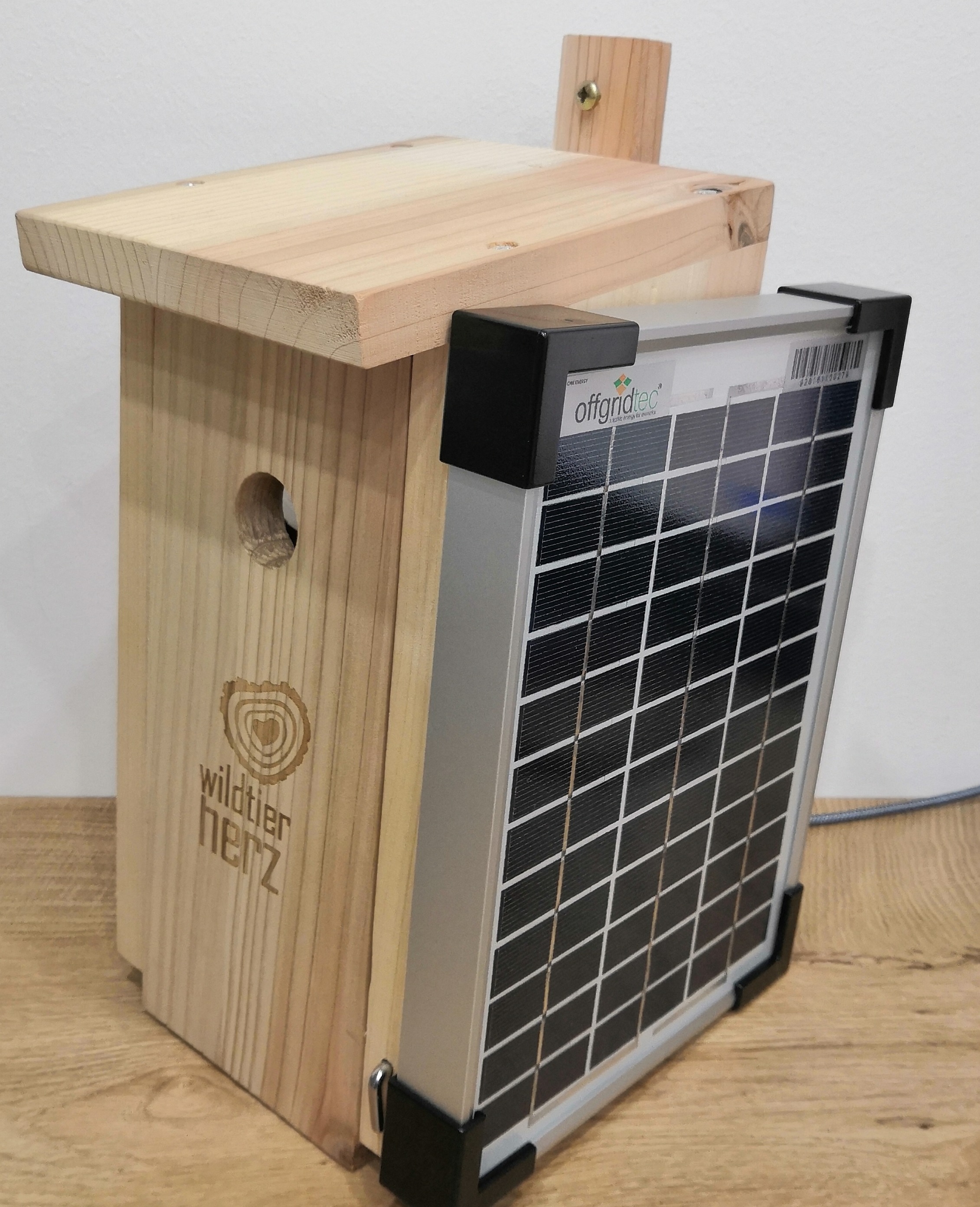
and an autonomous Nestbox for small birds with ESP32 connected to a Node-Red Backend (see photo below).
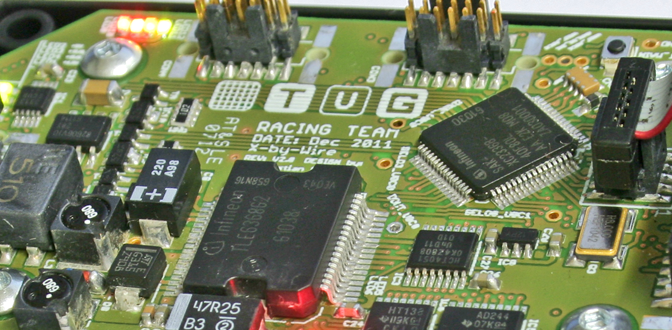
I’m glad to say, that after a few tests nearly the whole hardware on the new board ist fully functional now. The housing with the mounted connectors is also ready now to be put into the car.
A few Softwareupdates should also fit the X-by-Wire System to the Formula Student Electric Rules for 2012.
I expected to finish the whole board weeks ago, but i was busy with several other Projects. For example our Battery Management System – and the Powertrain testbench needed a lot of help, because due to some unecpected issues the installation and build-up was delayed by weeks… However it’s really exciting to see how all Systems in our car are getting more and more functional. Maybe i’ll post some pictures of our High Voltage Containment when it’s build up and give a few explanations how the Battery Management System (short: BMS) works in our car.
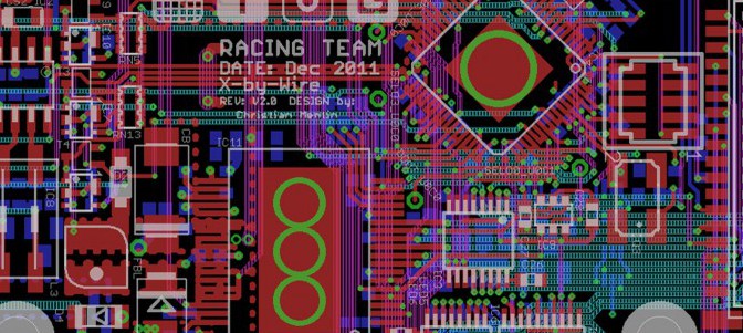
I’m glad to say that i got the chance to try something completely new for me. 4Layer pcb with 0,1mm lasered blind vias. When downsizing the pcb from last year my focus was on how low can i go with the amount of space.I searched for the smallest parts available, always looking forward in that way, that it has to be possible, to manually assemble the board.
After struggling with the new housing dimensions, i have to say that the X-by-Wire box would have been shrinked to 25% of the last years boxes volume. Due to the using of special connectors and having more than 40 I/O lines the size only shrinked down to 33% of the last years volume. I’m sure its a great step forward for me, because i never had the chance up to now, to use Blindvias for a PCB. Lets hope the boards arrive soon, AT&S is delivering more than 70 boards for the Racing team.
The new Board dimensions are 45x75mm compared to 115x90mm in 2011. This is over 65% PCB space savings! A good job i think…
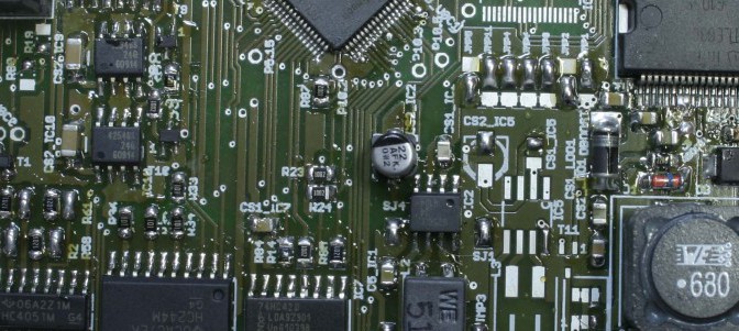
In cause of the heavy workaround needed to get the first PCB running, i decided to adopt the failures into a new revision of the x-by-wire board. Now it worked since the first assembly very good, so that i can focus on proramm the algorithms for checking the sensor values and communication with the electrical control unit of our car.
After hours of failure searching i found a mistake in the labeling direction of the footprint of xc2336B in my layout. This means that on every side of the microcontroller 10 pins were wrong labeled and therefore wrong connected. It took me a day to do some workarounds on the PCB with very tiny copper wires, but at least it worked out fine.