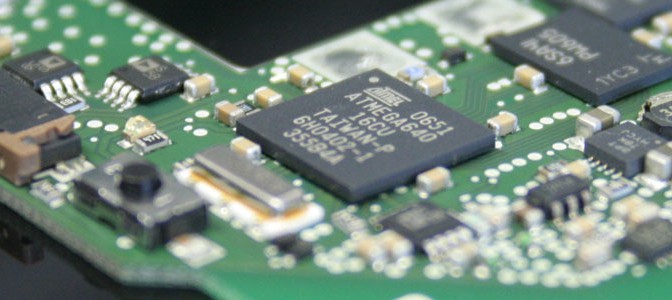
When designing Electronic hardware e.g. building a prototype, you might have to design Schematics and Layout by yourself, and if you want to save some money you may also assemble the electronic components on the PCB by yourself.
In this chapter i am going to show up some things that you may have to take into account when building a prototype, also considering some Problems you might do not want to get when looking further to series production.
- Component Libraries
- Schematic and Layout
- Assembly Process (SMT\THT)
- Electromagnetic Compatibility (EMC)
On one hand very important is, that the parts you are using can be assembled in a way of your choice. This means you may choose your design rules according to the assembly method. On the other hand when you are designing Schematics and Layout by yourself, you may have to take some standards or regulations into account. EMC is not only a big thing when you want to sell something, it’s also necessary for the whole electronic system to be functional and robust.
I will give you some Guidelines you can follow and also show you how to handle some Problems. These will be shown by time in this blog starting from scratch.

In principle i see 3 ways of assembly options for prototypes:
- manual assembly of all electronic parts without any use of reflow technology
(cheap and fast but maybe not suitable for all SMT Parts)
- manual assembly of all electronic parts with partly use of reflow technology
(relatively cheap and fast but suitable for nearly all SMT Parts)
- automatic\manual assembly by professional Assembler
(costly and takes additional 3-5 Weeks, but useful for all SMT Parts)
The first two points are in my opinion, suitable for many designs, where costs really matter, e.g. if you are prototyping something for yourself. Anyway the PCB designer has to consider these points when choosing the electronic components. When looking at my racing team Projects you may have noticed that all PCB’s there were assembled by myself only with one soldering tool. With a ERSA-icon nano and some different tips you can solder nearly everything you can see. There is no Problem with QFP or TSSOP Packages down to 0.5mm pitch. With that solder tool you can do this easily. But, if you have to use an IC which you only get in QFN, any other leadless Chip Carrier Package or BGA, you will have to use a reflow process for assembly.
Small reflow Systems are about 500€ overall costs. You will get good soldering results and you are approximately two times faster than if you only solder all parts by hand. When your designs starting to grow 50+ parts, it really makes sense to use such kits. So these small reflow systems might be the right choice for your project.
“Because of my last soldering results with such a tiny oven and direct comparison to the assembly results with fully manual soldering, this second option from above will really be my favourite choice for assembling homemade-semiprofessional PCBs. It works fine and it saves so much time”
How to set up your assembly process and what design rules you have to keep in mind when doing the Board Design will be shown in the upcoming posts.
Innovative Electronic Design – pushing the limits
