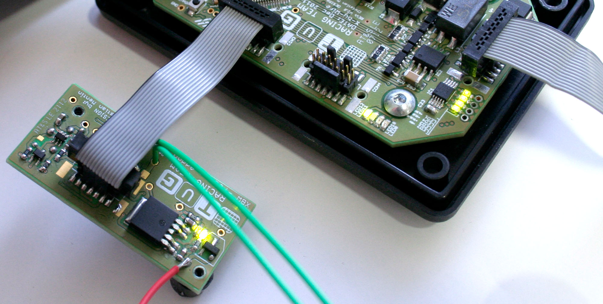
Today i’ve tested the new really tiny (20x41mm) Feature Addon Board V1.0 for the X-by-Wire Box 2012.
The requried Brake Panic Switch is now implemented this way, when the adjusted brake pressure is reached the car shuts down the power to the motors. The system can only be reset by the driver.
I’m really afraid of what some Formula Student Event Organizers think what we are doing but on 3rd of May there was a new rule in the reglement for FS Hungary was published. In order to get all systems working as soon as possible its really hard to understand how a new rule is developed so late this season…
B7.5 Brake Panic Switch B7.5.1 All electric vehicles must be equipped with a brake panic switch such
that in the event of a panic braking incident, the brake panic switch will
be activated and will turn off the traction system or any drive by wire
actuators. B7.5.2 The switch must be connected to the brake circuit such that it is
triggered at a pressure which is high enough to lock the wheels in dry
conditions. B7.5.3 The switch must be implemented with analogue components and not
through recourse to programmable logic controllers, engine control units,
or similar functioning digital controllers. B7.5.4 This system must latch until manually reset. This may be reset by the
driver in the driver’s cell. B7.5.5 The performance of the switch will be tested during the brake test.
There are several points i have to criticise.
The main point is, that such a panic switch has to be implemented only with non programmable logic. I do not understand that requirement, because if the pedal box is not functioning properly there will be other problems but surely not only by evaluating the brake preassure, aside from the short circuit and broken wire detection for each brake pressure sensor and additional plausibility checks.
If the performance of the switch will be tested at the brake test, the X-by-Wire Box has to function properly, otherwise the car won’t accelerate anyway.
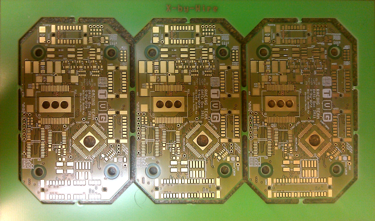
So the next days will be busy to design the schematic and the board for the required feature. Fortunately there is some free space in the X-by-Wire box, where the new, i’ll call it “Feature Addon Board”, can be placed.
The last days i was a bit struggeling with the Asynchronous Serial Interface of my last years Board. Today i realized that i have to rework my selfmade console whole from the bottom up but lets start at the beginning of the weekend…
As i mentioned already, the functionality of the new PCB would be the same as in the last year, only downsizing all components to minimum size. Last weekend i took the software and a reserve board from last year, to take a look at the integrated Watchdog of the X-by-Wire Multi Voltage Supply Unit (Infineon TLE6368).
After doing a bit debugging i realized that the printf’s i used for all debug statements were taking incredible long processing time. Time i cannot give for debugging, because a live debug when communicating with all systems in the car would not be possible anymore, because some printf’s take more than 10ms and for the Watchdog of the Supply Unit and the ECU in the Car, some critical Data (Watchdog Reset SPI and Throttle Postition over CAN) has to be provided within 10msCycle Time. This is a bit like a hard real time system, because the ECU needs the new data within the 10ms to avoid computing false parameters for the Motor Control Units…
So I decided to do some rework of my Software respectively the Asynchronous Serial Interface for Live Debug Support. Maybe i can post some pictures of the old debug Interface and the cycle times for the used printf’s…
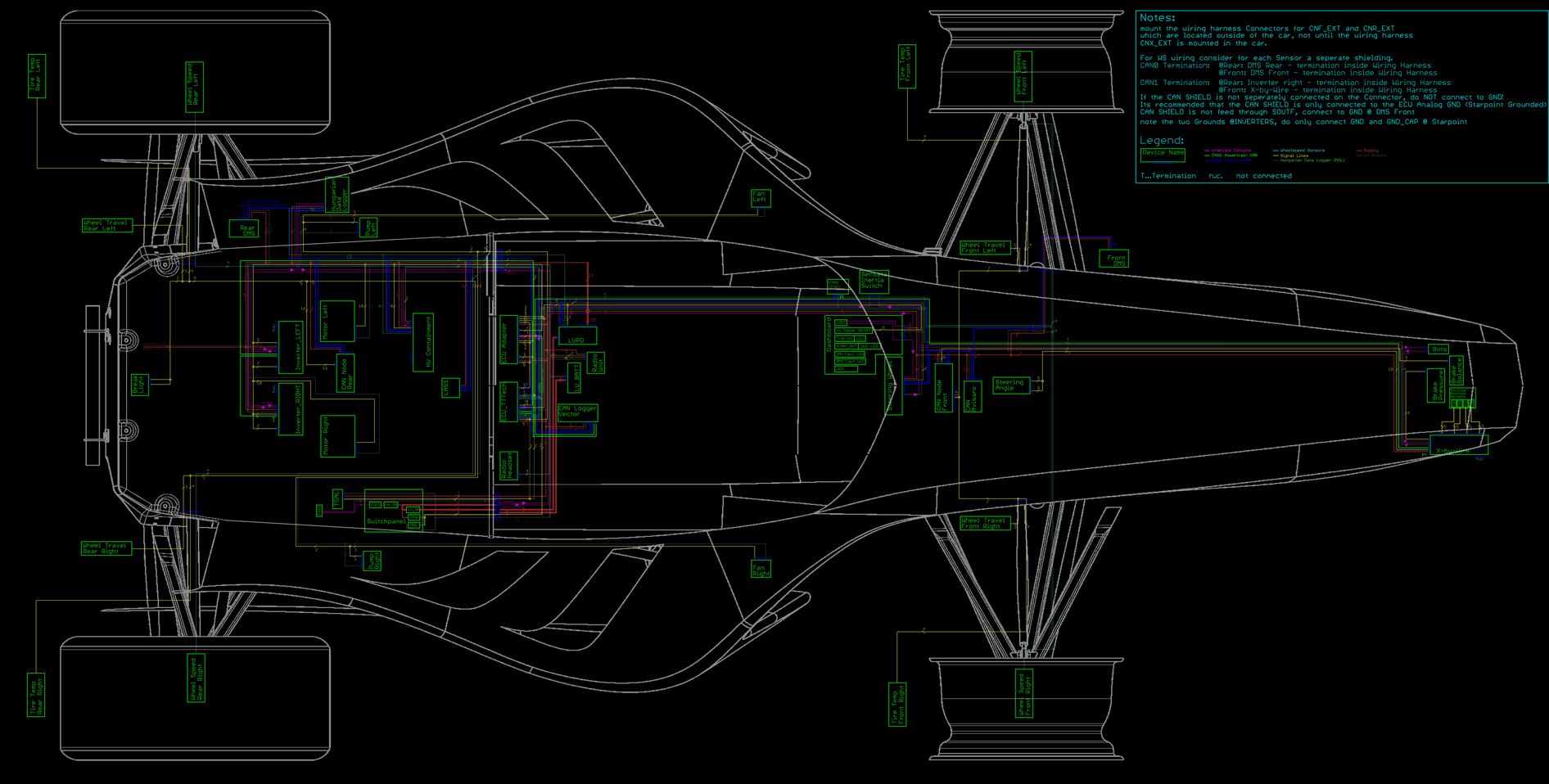
We have 46 sites of Excel sheets, to look into, for failures in connections between the devices in the electric car.
Because of being scared to oversee some wrong connections i decided to do a connection overview with all connections to make it simpler to inspect the whole wire harness of our car. It should also be easier when building up the wire harness to see what cables end where, and how much cables are going through the two bulk head feed through’s right and left beside the driver to boxes in the rear.