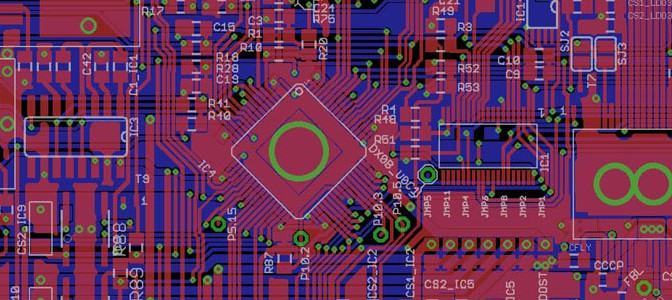
After hours of failure searching i found a mistake in the labeling direction of the footprint of xc2336B in my layout. This means that on every side of the microcontroller 10 pins were wrong labeled and therefore wrong connected. It took me a day to do some workarounds on the PCB with very tiny copper wires, but at least it worked out fine.
Due to production costs we decided to go a step further and integrate the functions of the Battery-Management-System – Master (short BMS master) also onto the X-by-Wire board. When the boards are ready we are going to assemble the PCB in two ways.
If its assembled in the first configuration with only one CAN Module and SPI Drivers, its the board with X-by-Wire function. The second configuration is with two CAN Modules, a RS232 Interface and no SPI Drivers, then it has to be the BMS master Board, wich monitors during charging our 400V cell stack, the voltage of every cell.
First job: develop a micro controller system to measure and approve pedal travel and steering angle, also called X-by-Wire System. “Fault tolerant and fail safe operation” is essential for cars, controlled with such systems.
Before the project start the micro controller Infineon xc2336B was choosen. Infineon is one of our main sponsors so we took controllers and other IC’s from Infineon. Very important is the mentioned fault tolerant and fail safe operation. The throttle pedal travel should be measured by redundant sensors and if one sensor fails because of cable break, sensor internal failure or shortcuts on any signal or supply wire, other sensors should not be affected. If redundancy of measurement is lost, the car has to be shutdown immediately. So we decided to use rotational magnetic field encoders from melexis, build up in a housing by megatron sensors.
One of my first full SMT Layouts was a analog to digital respectively digital to analog multi I/O card with a lot of op amp stages and a SPI digital to analog converter.
The main usage for these electronics was in industrial automatic test equipment. Several of this cards were connected in a stack to measure 80 Voltages and 20 Temperatures.