Today we’ve started the planning for the X-by-wire Box 2012. Last week someone said to me:
Whats that Box for? Sensing the pedals with such a big box? You must be crazy carrying that Box in your car around.
Sure, he is a combustion engine mechanic and he did not know that drive by wire systems must be safe in a way, that its fail-safe in every situation. In the car with combustion engine its the same as it was build in my VW Käfer: Bowden Cable back to engine. Not very innovative, but cheap and functional. In the electric driven car we need a extra micocontroller for that pedal “measurements”…
Mechanics always want to build a light car, you know. So that’s my job this year, building up a new X-by-Wire Box, same functionality but smaller and lighter has to be the slogan.
A few days now before the first contest for our car in England the x-by-wire system is now ready be put into the car.
Everything seems to be working fine for me, but the car is really struggling with several electrical and mechanical problems so that there is the possibility, that the car may be the first time driving in england on the racing track of silverstone.
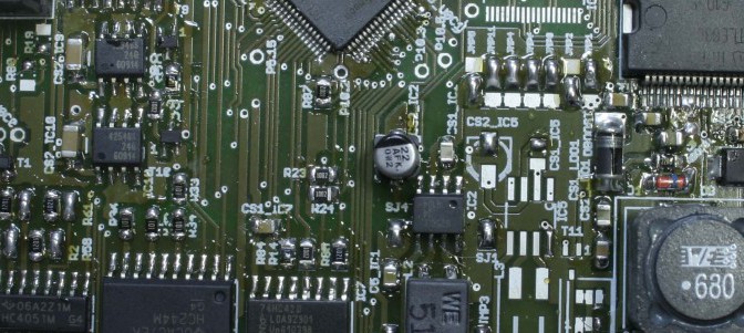
In cause of the heavy workaround needed to get the first PCB running, i decided to adopt the failures into a new revision of the x-by-wire board. Now it worked since the first assembly very good, so that i can focus on proramm the algorithms for checking the sensor values and communication with the electrical control unit of our car.
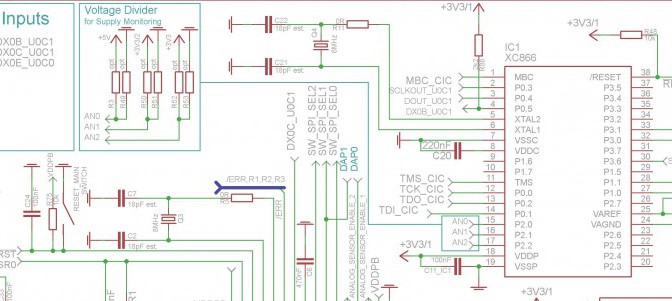
After hours of failure searching i found a mistake in the labeling direction of the footprint of xc2336B in my layout. This means that on every side of the microcontroller 10 pins were wrong labeled and therefore wrong connected. It took me a day to do some workarounds on the PCB with very tiny copper wires, but at least it worked out fine.
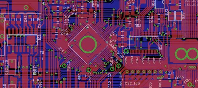
Due to production costs we decided to go a step further and integrate the functions of the Battery-Management-System – Master (short BMS master) also onto the X-by-Wire board. When the boards are ready we are going to assemble the PCB in two ways.
If its assembled in the first configuration with only one CAN Module and SPI Drivers, its the board with X-by-Wire function. The second configuration is with two CAN Modules, a RS232 Interface and no SPI Drivers, then it has to be the BMS master Board, wich monitors during charging our 400V cell stack, the voltage of every cell.