All posts by Christian

First steps with integrating RF Modules

In addition to the main system controller module as described in the post from June 12, i had to design something for me completely new. A RF Module has to be integrated for a Prototype ZWave to Industrial Analog Outupt:

  • 0-10V (default)
  • 0-5V
  • 0-20mA
  • 4-20mA

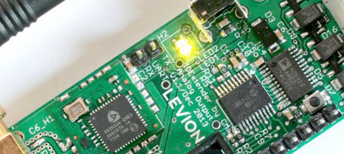
The ZWave Module is getting values from 0-255 from a ZWave Controller and these Values should be mapped to the DAC output. For this purpose i was going to use a tiny Microchip 8bit MCU (PIC18LF14K22) a DAC from Analog Devices, providing functionalities as described (AD5412) and a ZWave Module (ZM5202) for RF Communications connected via a serial Interface to the MCU. The RF Module has 50Ω Output Impedance, so for optimum RF Performance i had to design a 50Ω trace on the PCB for connecting a Antenna for  868,42 MHz.

Therefore i took a look into the Design Tool TXLine:

TXLine
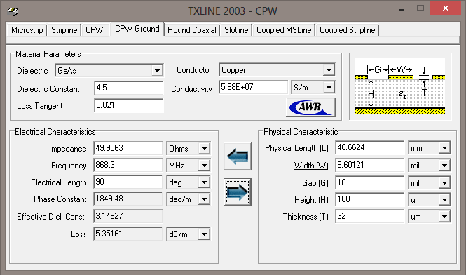
I considered a PCB Anenna Trace in the configuration “Coplanar Waveguide with Ground”. When using standard FR4 PCB Material you are going to expect a Dielectric Constant of 4.3 -4.7 and a Loss tangent of 0.021.

In a Layer Stackup when using 100um Prepreg and a Gap of 10mil im going to expect a Trace Impedance of 49.95Ω. In order to meet the requirements of the PCB Manufacturer i changed the Prepreg Thickness to 360um. 

IO_Extender
Antenna Trace as CPWG


Therefore the Trace dimensions and the Gap to the Top GND Plane had to be adopted. In order to get best HF-Performance on the PCB it is recommended that you guide the Antenna Trace, not only with the Top GND Plane, you also have to make this GND very “low inductive”. So placing additional GND Via’s near the Trace is a good idea. As it can seen on the picture i added many of them. In fact i never designed impedance controlled traces before, i added a PI Filter Structure for Antenna matching if necessary. First tests were made without any matching circuitry and the RF performance was good. So no further maching was done. During my research i found another useful Tool for designing Impedance controlled traces and differential pairs: Saturn PCB Design ToolKit. Its free, it does a good job and its really easy to use. I really recommend that Tool for every PCB designer to check the Impedance of critical Traces!

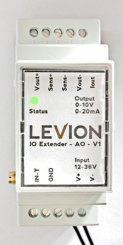
After some startup problems, i was getting better and better in understanding the ZWave Serial API. Coding the firmware for some essential functions (ZWave- inclusion\exclusion, Basic- set\get) was a  bit challenging but now it works fine. Acutal the Operating Voltage  is polarity protected and any Voltage can be choosen  between 10.8V and 36V. When mounted in the housing for DIN Rail mount it looks like this.

Distributed Microcontroller Systems – Delayed

Long Time no see 😉

But a totally new project is upcoming and consuming a lot of time. This project, which is similar to the Distributed Microcontroller Systems Idea, will be in addition used for my telematics semiar project

The only difference for me is, that i’m not goinig into the software part, its more proofing the hardware for satisfying the compliance of EMC/EMI standards. Furthermore some other important points have to be considered when designing PCB’s for series production.

The first prototype boards will arrive at the end of july and they will have the following components on board:

  • Freescale i.MX6 Quadcore CPU (512MB NAND Flash, 4x1GHz) edit: changed to Solo (1x1GHz)
  • WLAN, LAN
  • ZWave Option
  • USB Host
  • USB otg
  • HDMI
  • 7” Display + PCAP Touch

Till now i have designed many boards, but when thinking about the mentioned points this will really not be a simply PCB anymore. Therefore the developer team decided to take advantage from phytec developers, which are more confident with such complex designs, and develop the boards together with them.

So it’s clear, that this is a bit different to the original  Distributed Microcontroller Systems thoughts, but with additional Extensions it will become the more similar to the original idea. If i’m able to post more informations in detail or some pictures i will add it here immediately.

PCB Component Categorization

As i mentioned we decided to detect 0603 and 0805 case style Elements, and classify detected elements as Resistors or Capacitors. This was pretty hard, because you have to imagine, that if you are only looking onto a black and white image, some 0603 resistors can not be differenced from pads of unequipped parts. After hours of hard work the results can be shown:

Overview_V1.1-3

For that shown whole PCB we got very good results:

correct positives: 109 (out of 123)
false positives:      18
false negatives:    14
positive detection rate: 88,62%
precision:                             85,83%

Here a short comparison of the classification preformance to other Boards, where the results are not as good, but its still very impressive how good that works:

BV_Results

Microcontrollers choosen!

We decided to use some Microchip Controllers, because of the excellent Sample Service and the fact, that the Controllers are really cheap and available at the distributors like Farnell or RS-components. So for our Application we will take a closer look on following types:

  • PIC24F32KA304 for extreme low Power Applications (Deep Sleep down to 20nA)
  • PIC18F97J60 for Ethernet Applications (Integrated MAC 10Base-T)
  • MRF89XA as RF Transmitter
There is also a low cost RF Transmitter Module with PCB Antenna provided by Microchip, so we will take this Module for first tests.
For outdoor standalone Operation i was considering that this very cheap (3.29€) Solar Module with 4V and 35mA provides enough Power to operate the RF Transmitter Module. Everythings fine up to here so lets give it a try. The new IDE called MPLabX provided by Microchip is based on Netbeans IDE so I’m really taut if the free Microchip IDE + free Compilers can satisfy me.