Category Archives: Distributed Micocontroller System

The idea of distributed mcu’s

After finishing with the TUG Racing Team i wanted to try something different. My friend and I had the Idea to do some lightning and temperature measurements in our rooms or only switching on/off any device. Sure with an embedded microcontroller system its possible to switch and measure everything, assuming you have your hardware well designed.

But, if you are using microcontrollers you’ll often use some low layered interfaces to communicate with your device: e.g. you will have some buttons or an rs232 interface with a terminal on your pc.

Maybe you can go a step further and use TCP/IP communication but you will need an UI on your PC/Smartphone you are using. So thats the main point i was struggling the last years. The User changes his device for communication with the microcontroller system several times a day, using different Operating Systems.

Imagine you have a already proven Interface you can use for communication. With HTML and http its possible to use a Interface everyone is familiar, your Browser.

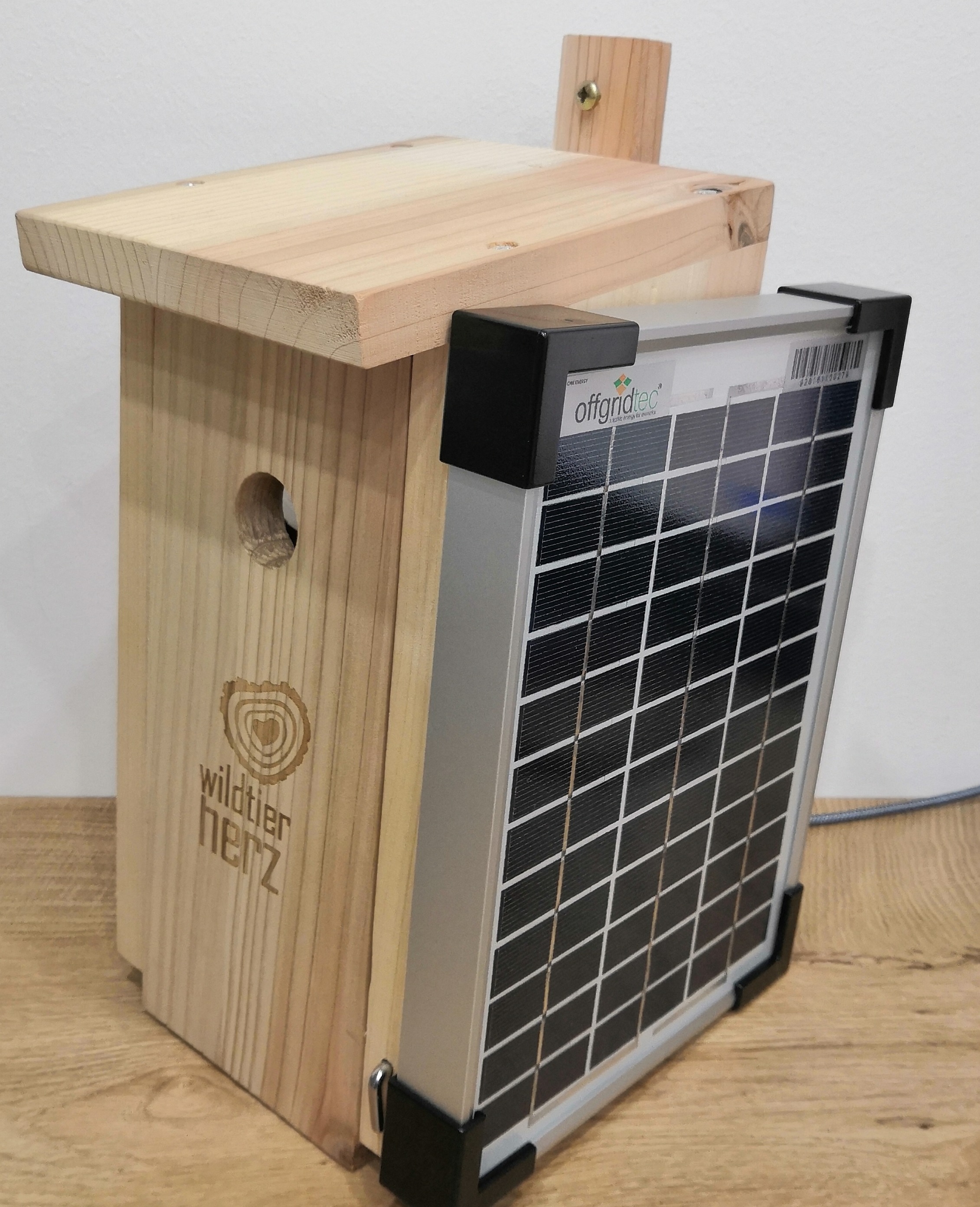
The Idea behind Distributed Microcontroller Systems (DMS)  is to have one microcontroller system, lets call it base station, in your home network, and several low power subsystems connecting wireless with a low cost RF Module to the base station. If you have a end device with the capability of having a browser you’re all in. The Idea is to have control over every subsystem only by connecting your browser to the main station. The low power Subsystems will be designed to operate in extremly low power mode so that battery or powering with a solarpanel is possible.

I’ll try to provide some more details or a block diagramm to show further details.

Long time no see ;)

Hi folks,

after having some tough time with finishing my PhD and digging into my new job as power electronics scientist at Silicon Austria Labs I had some time to prepare a few new things.

Finally the idea of microcontrollers, connected with webservers and capturing, storing and presenting data got a lot easier last years. So I kept up by working on ideas for IoT projects as my flat and garden definitely needed improvements towards automation and optimization (well that’s the computer engineers point of view).

Despite the fact that I decided to use well established standard WiFi technology with off-the-shelf IoT devices and collecting data on a web server to keep system design complexity minimal.

The initial idea behind my proposed distributed microcontroller systems project was the same – but at some point I realized, it’s damn easy with WiFi MCUs nowadays!

Especially with new technologies and Microcontrollers (as e.g. the ESP8266 and ESP32) with WiFi onboard a whole new era for easy integration with web 2.0 services had begun. And with that in mind I started several projects in parallel to make our home a bit more intelligent.

As teaser a short preview of what is upcoming in the next posts:

  • First steps with running Linux VMs & docker containers,
  • Setup of a reverse-proxy for proxied services (nextcloud & IoT devices),
  • Home and Garden automation using a selfmade API on an ESP8266, a python scripts in the Backend and a awesome Husqvarna Automower API,
  • and an autonomous Nestbox for small birds with ESP32 connected to a Node-Red Backend (see photo below).
BirdBox_V1.0
A nestbox for small birds – WiFi Cam included 😉

First steps with integrating RF Modules

In addition to the main system controller module as described in the post from June 12, i had to design something for me completely new. A RF Module has to be integrated for a Prototype ZWave to Industrial Analog Outupt:

  • 0-10V (default)
  • 0-5V
  • 0-20mA
  • 4-20mA

The ZWave Module is getting values from 0-255 from a ZWave Controller and these Values should be mapped to the DAC output. For this purpose i was going to use a tiny Microchip 8bit MCU (PIC18LF14K22) a DAC from Analog Devices, providing functionalities as described (AD5412) and a ZWave Module (ZM5202) for RF Communications connected via a serial Interface to the MCU. The RF Module has 50Ω Output Impedance, so for optimum RF Performance i had to design a 50Ω trace on the PCB for connecting a Antenna for  868,42 MHz.

Therefore i took a look into the Design Tool TXLine:

TXLineI considered a PCB Anenna Trace in the configuration “Coplanar Waveguide with Ground”. When using standard FR4 PCB Material you are going to expect a Dielectric Constant of 4.3 -4.7 and a Loss tangent of 0.021.

In a Layer Stackup when using 100um Prepreg and a Gap of 10mil im going to expect a Trace Impedance of 49.95Ω. In order to meet the requirements of the PCB Manufacturer i changed the Prepreg Thickness to 360um. 

IO_Extender
Antenna Trace as CPWG


Therefore the Trace dimensions and the Gap to the Top GND Plane had to be adopted. In order to get best HF-Performance on the PCB it is recommended that you guide the Antenna Trace, not only with the Top GND Plane, you also have to make this GND very “low inductive”. So placing additional GND Via’s near the Trace is a good idea. As it can seen on the picture i added many of them. In fact i never designed impedance controlled traces before, i added a PI Filter Structure for Antenna matching if necessary. First tests were made without any matching circuitry and the RF performance was good. So no further maching was done. During my research i found another useful Tool for designing Impedance controlled traces and differential pairs: Saturn PCB Design ToolKit. Its free, it does a good job and its really easy to use. I really recommend that Tool for every PCB designer to check the Impedance of critical Traces!

After some startup problems, i was getting better and better in understanding the ZWave Serial API. Coding the firmware for some essential functions (ZWave- inclusion\exclusion, Basic- set\get) was a  bit challenging but now it works fine. Acutal the Operating Voltage  is polarity protected and any Voltage can be choosen  between 10.8V and 36V. When mounted in the housing for DIN Rail mount it looks like this.

Distributed Microcontroller Systems – Delayed

Long Time no see 😉

But a totally new project is upcoming and consuming a lot of time. This project, which is similar to the Distributed Microcontroller Systems Idea, will be in addition used for my telematics semiar project

The only difference for me is, that i’m not goinig into the software part, its more proofing the hardware for satisfying the compliance of EMC/EMI standards. Furthermore some other important points have to be considered when designing PCB’s for series production.

The first prototype boards will arrive at the end of july and they will have the following components on board:

  • Freescale i.MX6 Quadcore CPU (512MB NAND Flash, 4x1GHz) edit: changed to Solo (1x1GHz)
  • WLAN, LAN
  • ZWave Option
  • USB Host
  • USB otg
  • HDMI
  • 7” Display + PCAP Touch

Till now i have designed many boards, but when thinking about the mentioned points this will really not be a simply PCB anymore. Therefore the developer team decided to take advantage from phytec developers, which are more confident with such complex designs, and develop the boards together with them.

So it’s clear, that this is a bit different to the original  Distributed Microcontroller Systems thoughts, but with additional Extensions it will become the more similar to the original idea. If i’m able to post more informations in detail or some pictures i will add it here immediately.

Microcontrollers choosen!

We decided to use some Microchip Controllers, because of the excellent Sample Service and the fact, that the Controllers are really cheap and available at the distributors like Farnell or RS-components. So for our Application we will take a closer look on following types:

  • PIC24F32KA304 for extreme low Power Applications (Deep Sleep down to 20nA)
  • PIC18F97J60 for Ethernet Applications (Integrated MAC 10Base-T)
  • MRF89XA as RF Transmitter
There is also a low cost RF Transmitter Module with PCB Antenna provided by Microchip, so we will take this Module for first tests.
For outdoor standalone Operation i was considering that this very cheap (3.29€) Solar Module with 4V and 35mA provides enough Power to operate the RF Transmitter Module. Everythings fine up to here so lets give it a try. The new IDE called MPLabX provided by Microchip is based on Netbeans IDE so I’m really taut if the free Microchip IDE + free Compilers can satisfy me.