Generating 3D Data
Every electronic designer may need a simple mechanical integration into a housing or only some protective shields for his electronic assembly.
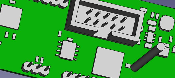
In my opinion the most critical point is, when some connectors have to be soldered directly onto the PCB or if they are mounted into the case walls and reaching far into the housing. In this case, some simple 3D PCB Information is sufficient to see if there are collisions, and if the whole assembly group fits into the housing. Well, this check may be part of the mechanical designer, but to ease this step 3D PCB Data is required.
So the Part of the electrical engineer is to generate 3D Data somehow :), which can be used by the mechanical engineer. I am generating STEP Files, which can be viewed with Free STEP Viewers, and integrated by every professional CAD Program.
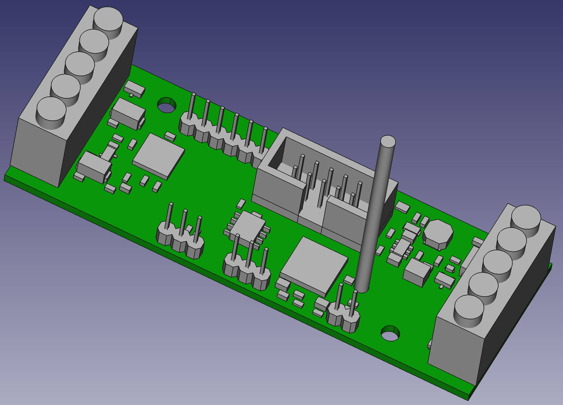
To generate this type of STEP Data is easy and can be done with EAGLE and a tiny tool, called idfstepper, within seconds. In this Tutorial i will describe this few steps, which are needed to setup all EAGLE part libraries to generate STEP data.